|

Understanding Retaining Walls
Prelude
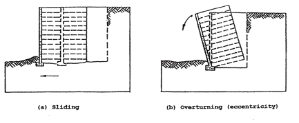
Proper installation of small and large retaining walls is critical to assure that the wall does not fail. The following 16 pages give an overview for any retaining wall structure. These 16 pages do not encompass all aspects but are intended to give an initial and basic understanding of proper retaining wall construction.
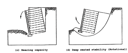
Retaining walls are frequently thought of as a stack of blocks or wood timbers with soil dumped behind those blocks or timbers. This is a project that will fail as days, weeks and months go by. If the installer does not understand the critical aspects of constructing a retaining wall, large commercial walls or small residential landscape walls, it is probable that one of the following types of retaining wall failure will occur.
The purpose of this introduction to the Maytrx Retaining Wall Book is to give information that applies to retaining walls. The information will be given for segmental block walls although much of this information can be applied to walls built with other face materials such as wood timbers. Segmental block walls are normally built with individual stones ranging in size from about ¼ square foot for the face area of each stone to 1 square foot face area or more for each stone. Characteristically, small residential retaining walls are built with the smaller stones while large commercial walls are built with the larger stones.
Retaining Wall Knowledge
Large retaining wall projects are normally called Mechanically Stabilized Earth [MSE] retaining walls while small retaining walls are normally called Gravity retaining walls. The major difference in these two types of walls is seen in the two drawings given here.
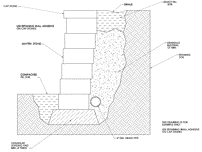
Gravity Wall
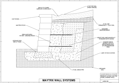
MSE Wall
Mechanically Stabilized Earth retaining walls built today use some of the same knowledge that was used in the Great Wall of China built as much as 1600 years ago. While the earth between the parallel walls that make up the Great Wall was stabilized with water reeds laid horizontally between layers of soil, current Mechanically Stabilized Earth retaining walls are characterized by placing layers of metal straps or strong synthetic grid material in a zone of earth behind the face stones. This is done to stabilize the soil in the retaining wall as the reeds have done for 1600 years in the Great Wall of China. Stabilizing the earth behind the face stones makes this stabilized earth zone become the principal part of the retaining wall. The face stones are a minor structural component of the stability of a Mechanically Stabilized Earth retaining wall.
Gravity retaining walls depend on the face stones to “retain” the fill soil behind the stones. The greater the set back slope [batter] of the gravity retaining wall, to a limit, the greater the ability of the stones to retain the soil placed behind the stones. Retaining walls are frequently 5 to 8 degrees off straight up. It is obvious that gravity retaining walls that are built with 0 degrees of batter, straight up, will fail with little horizontal force from the soil zone behind the face stones. It is important to take action that will minimize the horizontal force that the soil behind the stones will apply to the face stones. The proper action will be explained later in this Maytrx Book introduction. Typically, when the batter of a wall or series of tired wall exceeds 30 degrees off straight up the structure referred to as Reinforced Soil Slope [RSS] and is designed with different formulas than the formulas used to design retaining walls.
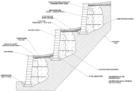
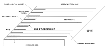
Tiered walls that exceed a 30 degree batter, RSS formulas will be used to design the overall structure
The Great Destroyer of all retaining walls is water. Referred to as hydrostatic pressure, water that is in the retained soil zone behind the retaining wall and/or the select soil zone can produce forces that will exceed or destroy the wall’s design. The principal reason is because, unlike unsaturated and compacted soil that imposes a small horizontal force on the face stones of a retaining wall, water that invades the retained soil zone or the select soil zone will put a horizontal force on the face stones that is equal to the water’s vertical force or weight. Also, too much water in the select soil zone will reduce the frictional characteristic of the select soil and then the select soil cannot provide the designed strength of the engineer’s design. Soil saturated by water will loose the internal forces that hold it in place, therefore the soil’s horizontal force on the face stones increases. Control of water in any of the soils and rock behind the face stones is perhaps the single most critical factor of both gravity and mechanically stabilized earth retaining walls. Design and construction of a swale at the surface behind the face stones of either type of retaining wall is critical if the surface soil does not slope away from the face stone toward the rear of the wall area. The swale must be designed to capture rain or other surface water and carry it away from the retaining wall. A drain tile system can be used for the same purpose.
To build a competent retaining wall of either type, gravity or MSE that will look good and serve its purpose of retaining soil for decades requires an understanding of many aspects of where the wall is to be built and how the wall will be constructed. The following information does not fulfill all knowledge necessary but will serve as an alert to owners, contractors and installers of what is important in retaining wall design. An understanding of the value of a competent design engineer for Mechanically Stabilized Earth retaining walls should be gained from this limited information.
The two types of walls will be discussed separately to eliminate confusion that may come from mixing a discussion of both types of walls in one all encompassing discussion.
Gravity Type Retaining Walls
Gravity type walls are normally for landscape applications and are usually built without geogrid or other stabilization material in the soil behind the face stones. These walls normally do not exceed 3 feet in height and if tired landscape walls are built the concepts of gravity walls may not apply. Tired landscape walls may require design as would a single wall that is of the total height of the multiple tired retaining walls.
The installer of a gravity type retaining wall needs to start by considering the location where the project is to be built. It is important that the installer study the area to determine if the soil upon which the retaining wall will rest is original virgin soil or can be compacted to carry the load of the new retaining wall. There must be no Karst topography under the retaining wall or the open cavities of the Karst topography must be stabilized. The area should be free of tree roots that may lift the face stones in the future. The installer can use paint or other marking material to mark the ground where the retaining wall will be built. Start the physical work by digging for a footing which will allow the installation of a leveling pad. The depth and width of the dig out must allow for the leveling pad’s thickness, usually about 1 inch thick for each 1 foot of wall height above the leveling pad. The leveling pad should be of fine material commonly called lime dust with some larger rocks in the mix up to 3/8 inch. This leveling pad must be compacted to a high density that will support the load of the face stones and leveled. The top of the leveling pad should be below the landscape grade in front of the wall by about 1 inch for each 1 foot of wall height above the leveling pad allowing for a toe of the retaining wall that is below the front grade. This toe prevents any sliding of the bottom layer of stones after the wall is finished.
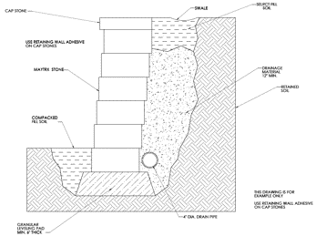
Gravity Wall
When the leveling pad is finished the first layer of retaining wall stones can be set making certain that the stones set flat and level. If the stones do not set flat and perfect, use small handfuls of sand where needed to do micro-leveling. If more leveling is needed, remove the stones and re-level and compact the leveling pad with the lime material. When the full bottom layer of stones are set and level, a perforated drain tube should be placed behind the stones with at least one end of this tube open to an area lower than the retaining wall’s leveling pad. This tube is for infiltrate water and should never carry more than a dribble of water. Infiltrate water is water that comes from internal to the soil behind the wall and small amounts of surface water such as rain water or sprinkler system water. Rain and any other surface types of water must be directed away from the retaining wall at the surface to prevent saturation of the soil behind the wall. Saturated soil may cause a retaining wall failure where the face stones move or collapse. Around the tube and for approximately 12 inches behind the retaining wall stones, install graded gravel of 1 inch or 1½ inch size. This single size gravel will allow any water that does infiltrate into the gravel zone to percolate down to the drain tube and away from the retaining wall. Fill behind the single size gravel fill with soil that is granular in nature not a clay type soil and compact to a high density. This will minimize the soil’s tendency to hold large volumes of water. Also, fill any grove in front of the bottom layer of stones and compact to hold the toe of the wall in place. Proceed by setting additional layers of retaining wall stones, placing 12 inches of single size gravel behind the face stones and the in the cores if core type stones are used. Then place soil behind the gravel and compact building up layer by layer. Placing and compacting the fill soil layer by layer as the wall is built is critical to prevent future settlement that can cause wall failure behind the wall face stones. Compaction equipment will not full compact several feet of fill. Compact the fill material in layers of 8 inches or less to assure good soil compaction throughout the height of the fill material. Compacting the fill soil behind the retaining wall also reduces the possibility that this soil will become saturated with water that will cause the retaining wall to fail.

 These two pictures show a retaining wall failure. The wall was not properly constructed for the application. The retaining wall is leaning forward and has separation between the individual stones. It appears that the wall stones were set with no batter. In this case it appears that water flowed into the area directly behind the wall saturating the soil behind the wall. This wall is surcharged due to the parking area near and directly behind the wall. It is likely that this application required a design engineer that would have designed the wall with geogrid to hold the surcharge of the parking lot and that a drainage system to assure that water did not collect in the soil behind the wall. A gravity retaining wall [no geogrid] may not have been adequate for this application. This small retaining wall’s failure shows that knowledge of retaining walls and proper construction is critical to all retaining wall applications. Inexperienced may lead an installer to think that gluing all stones together or the use of lip type stones will prevent a failure of a retaining wall like the one shown above. Glue and lip type stones will not prevent retaining wall failure. The hydrostatic pressure would have pushed this wall over regardless of gluing and use of lip type stones. Only proper design will prevent a retaining wall failure of the type shown in these photos. These two pictures show a retaining wall failure. The wall was not properly constructed for the application. The retaining wall is leaning forward and has separation between the individual stones. It appears that the wall stones were set with no batter. In this case it appears that water flowed into the area directly behind the wall saturating the soil behind the wall. This wall is surcharged due to the parking area near and directly behind the wall. It is likely that this application required a design engineer that would have designed the wall with geogrid to hold the surcharge of the parking lot and that a drainage system to assure that water did not collect in the soil behind the wall. A gravity retaining wall [no geogrid] may not have been adequate for this application. This small retaining wall’s failure shows that knowledge of retaining walls and proper construction is critical to all retaining wall applications. Inexperienced may lead an installer to think that gluing all stones together or the use of lip type stones will prevent a failure of a retaining wall like the one shown above. Glue and lip type stones will not prevent retaining wall failure. The hydrostatic pressure would have pushed this wall over regardless of gluing and use of lip type stones. Only proper design will prevent a retaining wall failure of the type shown in these photos.
For the top layer of the retaining wall stones it is advisable to use an adhesive manufactured specifically for retaining walls to glue the top stones to the layer below the top layer. Gluing the top layer to the layer below prevents vandalism and can avoid injury such as a single stone tipping if someone walks on the top layer.
At this point the stone part of the retaining wall structure has been completed. The soil behind the wall may be level or slope upward from the back of the face stones. Additional work is needed at the surface behind the wall to direct surface water such as rain water away from behind the retaining wall. Whether the soil is flat or slopes upward, build a swale in the soil behind the wall as shown here.

Design the swale such that it will flow surface water away from the wall rather than allowing the water to soak into the soil behind the retaining wall and saturating the compacted soil and rock behind the retaining wall.
A drain tile system can be designed if a swale cannot be built to carry surface water away. The drain tile may collect surface water behind the wall and carry the water away through tubes that are installed under the footing of the wall.
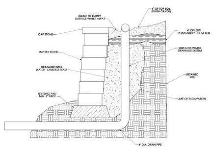
The preceding steps: 1. base soil that can carry the load of the wall with a leveling pad below grade establishing a toe to the retaining wall, 2.leveling and setting stones layer by layer with a drain tube placed in single size gravel to carry infiltration water away, 3.compacting the fill soil layer by layer behind the retaining wall and gluing the top layer to the next lower layer, 4.designing the surface soil with a swale behind the face stones to direct rain and other surface water away form behind the wall and 5. installation information specific to the retaining wall stones you use.
Following the proper installation methods will allow the gravity retaining wall you build to last for decades.
Mechanically Stabilized Earth Retaining Walls
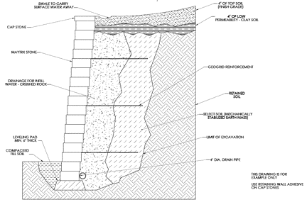
Mechanically stabilized earth retaining walls are normally larger projects but earth stabilization with geogrid materials may be necessary in walls as short a 3 feet or less. The load to be retained determines the need of the strength of the retaining wall. A generalized view of a cross-sectional drawing of a mechanically stabilized earth retaining wall structure is given here.
MSE Wall
The select soil, geogrid, crushed rock and face stones are a complete structure that is the retaining wall. The main body of this retaining wall, that provides most to the strength to hold the load of the retained material in place, is the geogrid reinforced select soil zone. The blocks that are used to face the retaining wall are a minor structural element of the complete retaining wall. The face stones do provide a critical element to the wall. This critical element is that they hold the select soil between layers of geogrid in place; they prevent sunlight’s UV rays from attacking the geogrid’s strength at the face of the wall; they provide an anchor for the front of the geogrid layers during construction.
The know-how that is needed to design a mechanically stabilized earth retaining wall and to design the area where the mechanically stabilized earth retaining wall will be built is of utmost importance. Segmental retaining wall engineers and geotechnical engineers work together in the design of the mechanically stabilized earth retaining wall and the area where the wall will be built. All steps of their work are based on information that is determined by their research of the area and information provided by others such as laboratory results of the soil characteristics and strength of the geogrid.
Information concerning the area, in front of and behind the wall structure, must be obtained to determine if the soil that is currently in place where the wall is to be constructed is of sufficient strength to support the mechanically stabilized earth retaining wall. Typical geogrid depths behind the face stones may be from 4 to 12 feet although the design engineer will determine the geogrid depth. It is obvious from the drawing given above, that the mass or weight of the mechanically stabilized earth retaining wall is large. This large mass must be supported by the soil below the mechanically stabilized earth retaining wall. Typically bore holes are drilled to determine the characteristics of the area. This may find poor quality soil for support or other problems such as sink holes and Karst topography. During the study of the area, any knowledge of underground water flows that must be drained away may be found. Sometimes these underground water flows are not located until the dig-out for construction of the mechanically stabilized earth retaining wall.
If the soil at the location will not adequately support the mechanically stabilized earth retaining wall then the retaining wall engineer will design a soil base for the mechanically stabilized earth retaining wall that may include soil replacement or soil treatment to strengthen the base soil or some type of caissons for structural support or other methods to strengthen the base soil. If the base soil is not adequate to support the mechanically stabilized earth retaining wall the structure can settle downward more than an acceptable amount or there may be global failure of the complete structure as shown here.
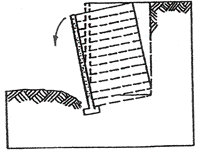
Global failure due to weak foundation soils
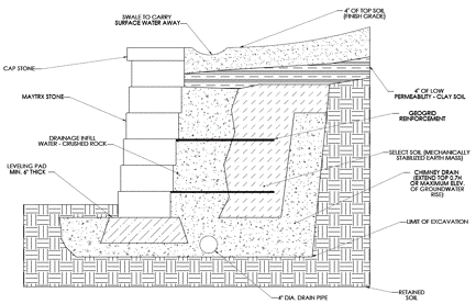
If a ground water zone is found, the engineer will design a system that will capture the water and carry it away from behind the mechanically stabilized earth retaining wall. If this water is not removed it can saturate the reinforced zone and cause failure of the wall by changing the internal strength of the reinforced soil zone of the mechanically stabilized earth retaining wall and by adding a large horizontal load behind the retaining wall. An example of a drainage design called a Chimney Drain is shown here but other designs may be given by the engineer.
With all external data known the retaining wall engineer can design the mechanically stabilized earth retaining wall structure. In this brief presentation it is impossible to cover all aspects of the mechanically stabilized earth retaining wall design yet many of the important design factors can be presented followed by rules of thumb. The owner of the wall is the ultimate responsible party. It is the owner that hires the design engineer and contractor for his project. It is the owner that is responsible for assuring that competent personnel are working on the project and that personnel are employed to cover all aspects of the wall’s design and construction. It is critical that not only the design work be competent but that the construction of the mechanically stabilized earth retaining wall structure is completed as designed. Construction oversight by the design engineer’s company or a third party with knowledge of proper installation of mechanically stabilized earth retaining walls is critical. The drawing below shows the major elements of a mechanically stabilized earth retaining wall. Using this drawing some critical aspects of the construction of a mechanically stabilized earth retaining wall will be given. General information will follow that will allow the owner to ask questions of the engineer, contractor and person providing daily installation oversight of the construction.
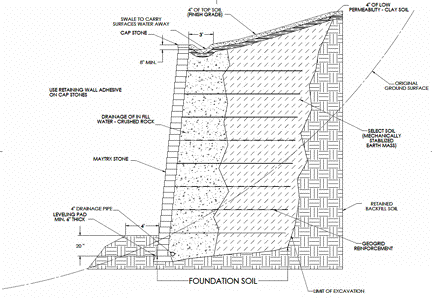
The drawing shows 1. Facing, 2. Front bench, 3. Leveling pad, 4.Foundation soil, 5. Drain tube and clean gravel for infill water, 6.Mechanically stabilized earth mass, 7. Geogrid, 8. Finished grade, 9. Retained backfill, 10. Original ground surface, 11. Limits of excavation. A brief discussion of each will be given noting some critical factors.
- Facing – The facing stones are of various types. Stones are to be manufactured to specific standards, usually designated as a 3000 pound crush test and less than 5 % water absorption after 24 hours. Most stones are designed with a layer by layer set back that will develop a batter in the face of the wall. Batters are frequently 5 to 8 degrees off straight up. Although there are many options to control each layer’s set back the most frequently seen are the use of pins that fit in holes in the stones and a lip or knob on the front or back of each stone. All of these designs rely on friction to hold the geogrid in place after the mechanically stabilized earth retaining wall is finalized. It has been determined in testing that rear lips on stones can cut the geogrid at high stresses, reducing the tie between the face stones and the mechanically stabilized earth zone. These high stresses occur in the lower layers of a tall retaining wall. Also, these rear lip stones do not allow the geogrid to lay flat across the stone, the rock placed behind the stones and the soil in the stabilized zone. To back to avoid damage to the geogrid fibers, geogrids must be laid flat from front to back. Generally speaking, the use of stones that are flat or have front lips or other set back control such as “knobs” near the front of the stones will allow the geogrid to tie to the face stones without cutting the geogrid. Cut geogrid will affect the strength of the tie between the face stones and the rock - stabilized soil zone behind the face stones. Core face stones require that the cores be filled with single size gravel as each layer of stones is placed. Core type stones that have the cores filled with gravel give excellent friction to geogrid material.
- Front bench – For walls that have sloping soil in front of the wall, a bench that is a minimum of 4 feet wide should be constructed in front of the wall. This will prevent the front soil from sliding away and reducing the designed embedment of the wall.
- Leveling pad – The leveling pad surface must be strong enough to carry the load of the face stones without compacting unevenly. This pad is usually a non-reinforced ready mix or compacted fine limestone mix. The leveling pad will allow the minor settlement that will occur after the wall is constructed. The use of modular blocks for the face of the retaining wall allows the minor settlements without a noticible change to the appearance of the face of the wall. The leveling pad may have step-ups or step-downs along the length of the wall face depending on the grade of the soil. As the slope of the soil changes from one end of the wall to the other end the step-ups or step-downs must allow for the design embedment of the mechanically stabilized earth retaining wall.
- Foundation soil – The foundation soil must carry the huge load of the complete mechanically stabilized earth retaining wall structure as previously discussed.
- Drain for infill water - This tube is for infiltrate water and should never carry more than a dribble. Infiltrate water is water that comes from internal to the soil behind the wall with a minimum of surface water such as rain water or sprinkler system water. Rain and any other surface type of water must be directed away from the retaining wall at the surface to prevent saturation of the soil behind the wall and near certain retaining wall failure. Around the tube and for at least 12 inches behind the retaining wall stones, install graded gravel of 1 inch or 1½ inch size. This single size gravel will allow any water that does infiltrate into the gravel zone to percolate down to the drain tube and away form the retaining wall. To build the wall to the design strength it is imperative that the clean backfill gravel be placed as every level of stones are set. If core units are used the cores of each stone must be filled as each layer of stones are set. Completely filling core stones and placing the gravel behind the stones as each layer is placed will provide for the structural interlock of the geogrid and rock that is necessary to meet the design strength of the mechanically stabilized earth retaining wall.
- Mechanically stabilized earth mass – This zone includes the select soil, clean graded rock and the geogrid used to develop the majority of the retaining wall’s strength. The clean single size rock should be placed for at least 12 inches behind and between the face stones. If the face stones are core units, it is important to have the cores of each stone totally filled with the clean gravel as each layer is installed. Failure to install the rock fill layer by layer will cause the tie between the face stones, the rock, the soil and the geogrid behind the face stones to be significantly lower than the test data used in the design of the retaining wall. Additionally, it is important that the soil be designated by the wall engineer. In some cases the local soil can be used but in other cases the local soil will have high clay content or organic material that is not acceptable for the stabilized zone. The select soil will be described as granular and have high flow characteristics [permeability] to allow infill water to move to the drain tube. This select soil will have high compaction characteristics allowing the friction between the soil and the geogrid to be maximized. This soil should be compacted in lifts equal to the height of the modular stones or 10 inches whichever is less. For the first three feet behind the face stones the wall installer is to use hand compaction equipment, heaver equipment can be used behind this zone.
- Geogrid – The geogrid is often a strong polyester (PET) fiber that is coated with poly-vinyl-chloride (PVC) to provide rigidity to the geogrid matrix although some other types of grid material are available. The PVC can degrade when exposed to the sunlight’s ultra violet (UV) rays. Geogrid should be stored to avoid exposure to sunlight. The geogrid must be laid on a flat surface of face stone-clean gravel-select soil fill to prevent damage to the grid that will reduce its strength below the manufacturer’s stated strength that is used by the design engineer. On-site engineering oversight is critical at this step. The oversight engineer is to assure that all openings between stones and stone cores are full of clean gravel and that the gravel and soil fill behind the face stones is dead level to avoid wrinkles and cutting by the back of the stones. That the geogrid is pulled taunt and staked at the rear to assure that the geogrid will start stabilizing the total wall mass immediately after construction of the wall. Non-taunt geogrid will not stabilize the total wall mass until the geogrid is pulled taunt by movement of the wall mass ultimately making the geogrid taunt. All grid materials can be damaged during compaction. Compaction or other equipment should never be driven directly on the geogrid. Fill material should be placed on the geogrid material ahead of the tires or tracks of the wall building equipment. In special applications such as water front retaining walls the type of geogrid is potentially critical. Polyester fibers degrade in high alkaline and high acidic environments. Modular blocks in a water front environment may cause long term high alkalinity near the wall face. Polyolefins appear to degrade only in high acidic environments and may be preferred for waterfront wall structures built with modular blocks.
- Finished grade – The finish grade and any structures that are or will be built above the retaining wall are necessary to the design of the mechanically stabilized earth retaining wall. Upward sloping soil and structures such as roads and buildings above the wall are additional loads to the retaining wall and must be incorporated into the wall’s design. Rain and any other surface type of water must be directed away from the retaining wall at the surface to prevent saturation of the soil behind the wall and near certain retaining wall failure. A swale built behind the wall near the face stones that is properly terraced will flow surface water away from the wall rather than allowing the water to soak into the soil behind the retaining wall and saturate the compacted soil behind the retaining wall. Other drain systems may also be designed.
- Retained backfill – The retained backfill is the non-reinforced soil that is behind the mechanically stabilized earth retaining wall structure. This soil will normally be of lower quality than the select soil in the stabilized zone. The retained backfill must be compacted in adequately thin lifts to obtain the design engineers specified density of the retained soil throughout the total height of the wall structure. The engineer responsible for construction oversight has the responsibility to assure that this zone is properly constructed.
- Original ground surface – The original ground surface may require a dig-out to build the mechanically stabilized earth retaining wall structure. During excavation a ground water zone may be found. As shown and discussed previously the wall design engineer will design a system that will capture the water behind the stabilized zone and carry this water away from the mechanically stabilized earth retaining wall. A drawing of one type of system, a Chimney drain was given earlier.
- Limits of excavation – The limit of the excavation defines the amount of soil that will need to be removed, and possibly hauled away from the site to properly construct the mechanically stabilized earth retaining wall structure. This may include digging deep to build a foundation for the complete structure.
Some problems that have been identified in commercial retaining wall structures are 1. poor specifications; 2. misapplication of retaining wall technology; and 3. lack of specification enforcement. Poor Specifications are normally due to a lack of knowledge or understanding. In large commercial retaining walls it is critical that the engineer have experience and cover, as a minimum, the items that are discussed in this paper. In small landscape retaining walls, specifications are not normally written yet the installer, homeowner or landscaper, must know and follow similar procedures to build a structure that will perform and look good for decades. Misapplication of retaining wall technology is a key to many retaining wall failures. For example, many people believe that a physical lip on a retaining wall block is of value in preventing retaining wall failure. Technology shows that the weight of the stones, actually the mass, is critical; lips on stones are not a structural asset and lips can actually cut the geogrid in high stress applications. The overriding technological factors are proper construction of the retaining wall, including the fill zone behind the face stones. Lack of specification enforcement during construction occurs too frequently when the owner expects to save cost by reducing or eliminating wall construction oversight. Even on large commercial walls oversight may be eliminated or limited in scope. This is a mistake. Local government inspection is not present continuously and cannot assure that all layers of the retaining wall are built as specified by the design engineer. The proper construction of a retaining wall as described in the engineer’s plans may seem to include unnecessary steps to some contractors and wall installers. During construction of the wall some steps may be eliminated or modified and the result is that the design strength of the retaining wall is reduced which may lead to a failure of the retaining wall. One frequent construction error is to not fill cores of core type stones as every layer is set in place. Another construction error is the placement of several layers of stones before placing the gravel and select soil behind the stones. This construction error often leads to inadequate compaction of the select soil zone.
The preceding points that discuss mechanically stabilized earth retaining wall structures do not cover all aspects that may be critical to any retaining wall structure but do give a idea of the value of the design engineer, the geotechnical engineer or engineering geologist, the contractor or installer and the oversight engineer all working to provide the owner with a properly built retaining wall that will have a design life of 75 to 100 years.
For the owner of a mechanically stabilized earth retaining wall structure the following rules-of-thumb can be used to ask questions to check the design of your retaining wall structure. These rules-of-thumb are not all encompassing but can initiate conversation to address all steps that are covered in a mechanically stabilized earth retaining wall structure’s design.
What is the depth of the geogrid?
Answer: Grid depth is normally = 0.7 X [the walls total height] (from leveling pad to top)
What is the spacing of the geogrid layers?
Answer: 2 X [The depth of the modular block]. If stone is 12 inches front to back space geogrid every 24 inches.
What is the embedment of the wall?
Answer: Minimum is 20 inches except when on rock. Slope in front of the wall will increase embedment depth.
What is the bench width in front of the wall? (For walls with downward slope in front)
Answer: Minimum 4 foot bench width in front of the base of the face stones.
Additional items to address when having a retaining wall built:
All modular block units shall be sound, free of cracks, or other defects that could interfere with proper placing of each unit. The unit will not impair the strength or performance of the SRW [segmental retaining wall].
All SRWs will be constructed utilizing only products, such as adhesive or pins that are supplied or approved by the company that designed and licenses the units for production.
All modular units shall be handled, stored and shipped in such manner as to eliminate the dangers of chipping, discoloration, cracking, fracturing and other excessive stresses.
Modular units must be manufactured to gauge. Stresses that are imposed upon units that are artificially leveled with shims may result in a SRW that does not meet the design engineer’s criteria. Pullout test and other test results will not be applicable to shimmed units.
Modular units should meet or exceed a 3000 psi crush test and have no more than 5% water absorption after 24 hours by weight.
Geogrid should be stored to avoid UV rays.
Geogrid must be installed as given in the design engineer’s plans. No wrinkles are allowed and the geogrid must be dead level and continuous, no cuts, from front to back. Rear lip type stones will cut geogrid at high stresses.
Geogrid should contact rock, stones and soil only. Do not overlap layers of geogrid.
Reinforced Soil Slopes [RSS]
Reinforced Soil Slopes [RSS] are typically not built using modular blocks but do use geogrid. The formulas used by the engineers to design Reinforced Soil Slopes are a different set of formulas. Typically, RSSs are faced with shrubs or some rubble rock material. There are situations where the design engineer will use RSS formulas with tired modular block walls. In these cases the overall slope of the walls will be 30 degrees or more off straight up. Generally speaking, the separation between using retaining wall design formulas and slope design formulas is that if the overall slope is less than 30 degrees off straight up then retaining wall formulas are used to design the structure and if the overall slope is greater than 30 degrees off straight up-slope formulas are used.
For the full book download click here. | 
